Vector forces
This understanding of vectors enables us to estimate the tension in rope systems.
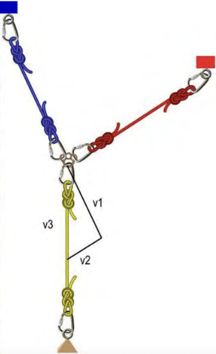
In this diagram we have a 100kg mass suspended by an anchor system focused at a rigging plate. Using the language of vector physics, for the system to be at equilibrium (ie the anchors, the mass and the rigging plate are stationary), all of the forces acting on the rigging plate must cancel each other out – or add up to equal zero.
Previously we discussed that vectors can be used diagrammatically to represent forces. Conventionally this is done with straight lines where the line length is proportional to magnitude and the arrowhead indicates the direction of application.
The rigging plate has three ropes pulling it in different directions. The force, or tension, in the vertical rope is that produced by the 100kg mass (about 1kN) – this we can call ‘v3’ and it pulls down on the plate. The other two ropes pull on the rigging plate to oppose ‘v3’ with forces ‘v1’ and ‘v2’. If the rigging plate is stationary, then the three forces must “add” up to zero. The triangle to the right of the rigging plate demonstrates this vector addition. Each vector is drawn head to tail and ‘v1’ + ‘v2’ + ‘v3’ = 0.
The ‘magnitude’ of the vectors ‘v1’ and ‘v2’ can be measured relative to the known length of ‘v3’ (expressed as 100kgf). Note that this can be estimated in the field by drawing lines in the dirt near the anchor focal point and then using string or sticks to estimate the relative lengths of the three sides of the triangle.
In this example, careful measurement yields that, when a mass of 100kg is suspended, the blue anchor ‘feels’ a pull equivalent to 85kg and the red anchor ‘feels’ 43kg. Technically, we should say:
- The 100kg mass applies a force of 1kN (actually 0.98kN) to the rigging plate
- The left anchor experiences a force of 0.85kN (or 0.833kN)
- The right anchor experiences a force of 0.43kN (or 0.421kN)
Note also that vector addition is quite different to straight mathematical addition and that 43kg + 85kg does not equal 100kg.
Vector forces become apparent whenever there is an internal angle greater than 0° between two or more rigging components or anchorage points.
For ease of explanation, a vector force is typically trying to pull horizontally as well as vertically. This has a multiplying effect on the loads that are felt at the anchor points and likewise the tension exerted within the rigging equipment, be it ropes, slings, strops or chains.
Force is an influence that has both magnitude and direction, it is usually given in the dynamic unit of Newtons (N). For ease of explanation we have used kilograms on this page.
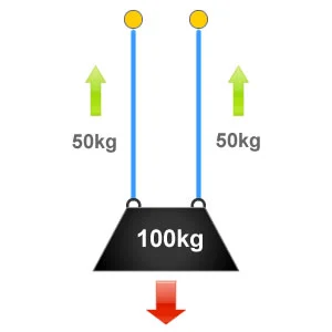
In the situation illustrated to the right, the weight of the load = 100kg. The load is supported by two slings of equal configuration with no internal angle, so 100kg / 2 = 50kg. This means that each sling and anchor point is being subject to 50kg or 50% of the loads weight.
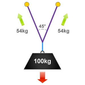
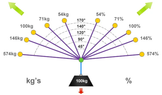
When rigging ropes the ‘ideal angle’ is approximately 45°, at the ideal angle there would be 54% of the loads weight being distributed to each anchor device. Although this is over half of the original weight of the load we have still gained an advantage by sharing it between the two anchor points.
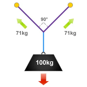
An internal angle of 90° between ropes and rigging components is sometimes referred to as the ‘OK’ angle. At this angle 71% of the loads weight will be distributed to each anchor component, so in this example that will be 71kg.
It is often easier to roughly estimate a 90° or right-angle when undertaking rigging tasks. By staying at or below this angle ensures that we don’t load our anchor components with excessive forces.
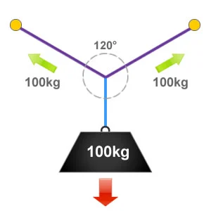
A basic way to understand the effect of vector forces is to imagine that if a full circle equates to 360° and this was split into three equal parts we would end up with three angles of 120°, as show in the illustration on the right. An internal angle of 120° is also defined as the ‘critical angle’.
Because everything is in equilibrium at the critical angle of 120°, whatever the load weighs is what we have being exerted to each anchor point and each item of rigging equipment. So in this example it is 100kg or 100% of the loads weight.
Vector forces can be calculated using mathematical formula. So far on this page we have used kilograms to represent the loads in the illustrations. As a kilogram is a measurement of mass, this should be converted to weight (Newtons) to calculate the resultant force correctly. Force is an influence that has both magnitude and direction, it is usually given in the dynamic unit of Newtons (N). For simplicity we have used kilograms for the examples on this page.
Providing that the rigging components are sharing the weight of the load equally, such as in a ‘Y’ hang then the following equation can be used to get load applied to each component: